IFM
IFM PQD384 Pressure Sensors
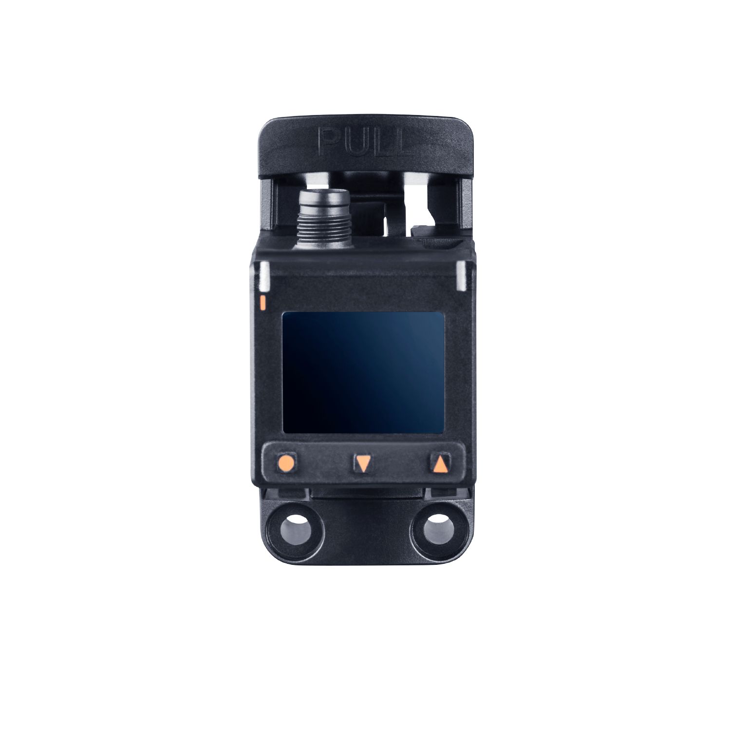
Pressure sensor for pneumatics
IFM PQD384 Pressure Sensors — datasheet, specifications, part number lookup & authentic sourcing
Get a Quote / Inquire
Product Highlights
- Reliable monitoring of the system pressure in pneumatics and in compressed air systems
- Very high overpressure and vacuum resistance
- Clearly visible TFT display
- Red/green display for clear identification of the acceptable range
- With programmable switching output and analogue output
- Convenient operation via buttons or parameter setting via IO-Link
Overview
| Product designation | Electronic pressure sensor |
| Application | for industrial applications |
| Process connection | threaded connection G 1/8 internal thread (2x) |
| Operating voltage DC | 18...30 V |
| Voltage type | DC |
| Electrical design | PNP/NPN |
| Total number of outputs | 2 |
| Output function | normally open / normally closed; (parameterisable); analogue |
| Output signal | switching signal; analogue signal; IO-Link; (configurable) |
| Analogue current output | 4...20, invertible; (scalable) mA |
| Analogue voltage output | 0...10 / 1...5, invertible; (scalable) V |
| Measuring range | -1...10 bar-14.5...145 psi-0.1...1 MPa |
| Connection | M8 Connector |
| Materials | PBT; PC; TPE; NBR; FKM; brass; silicon (coated) |
| Materials (wetted parts) | PBT; FKM; brass; silicon (coated) |
| Display | Display 1": 128 x 96 pixels; switching status: 1 x LED yellow |
| Ambient temperature | 0...60 °C |
| Medium temperature | 0...60 °C |
| Communication interface | IO-Link |
| Brand | ifm electronic gmbh or equivalent |
| Type | PQD384 |
Specifications
| Product characteristics | |
| Number of inputs and outputs | Number of digital outputs: 1; Number of analogue outputs: 1 |
| Measuring range | -1...10 bar -14.5...145 psi -0.1...1 MPa |
| Process connection | threaded connection G 1/8 internal thread (2x) |
| Application | |
| Special feature | Gold-plated contacts |
| Application | for industrial applications |
| Media | compressed air; nitrogen (N2) |
| Conditionally suitable for | other media on request |
| Medium temperature | |
| 0...60 °C | 32...140 °F |
| Min. burst pressure | 20 bar 290 psi 2 MPa |
| Pressure rating | 15 bar 220 psi 1.5 MPa |
| Vacuum resistance | -1000 mbar -14.5 psi -0.1 MPa |
| Type of pressure | relative pressure; vacuum; differential pressure |
| Electrical data | |
| Operating voltage[V] | 18...30 DC |
| Current consumption[mA] | < 30 |
| Min. insulation resistance[MΩ] | 100; (500 V DC) |
| Protection class | III |
| Reverse polarity protection | yes |
| Power-on delay time[s] | 0.3 |
| Integrated watchdog | yes |
| Inputs / outputs | |
| Number of inputs and outputs | Number of digital outputs: 1; Number of analogue outputs: 1 |
| Outputs | |
| Total number of outputs | 2 |
| Output signal | switching signal; analogue signal; IO-Link; (configurable) |
| Electrical design | PNP/NPN; (configurable) |
| Number of digital outputs | 1 |
| Output function | normally open / normally closed; (parameterisable) |
| Max. voltage drop switching output DC[V] | 2.5 |
| Permanent current rating of switching output DC[mA] | 100 |
| Switching frequency DC[Hz] | < 170 |
| Number of analogue outputs | 1 |
| Analogue current output[mA] | 4...20, invertible; (scalable) |
| Max. load[Ω] | 500 |
| Analogue voltage output[V] | 0...10 / 1...5, invertible; (scalable) |
| Min. load resistance[Ω] | 2000 |
| Short-circuit protection | yes |
| Type of short-circuit protection | pulsed |
| Overload protection | yes |
| Measuring/setting range | |
| Measuring range | -1...10 bar -14.5...145 psi -0.1...1 MPa |
| Set point SP | -1...10 bar -14.5...145 psi -0.1...1 MPa |
| Analogue start point | -1...8 bar -14.5...116 psi -0.1...0.8 MPa |
| Analogue end point | 1...10 bar 14.5...145 psi 0.1...1 MPa |
| In steps of | 0.01 bar 0.1 psi 0.001 MPa |
| Accuracy / deviations | |
| Switch point accuracy[% of the span] | < ± 0,5; (turn down 1:1) |
| Repeatability[% of the span] | < ± 0,1; (with temperature fluctuations < 10 K: turn down 1:1) |
| Characteristics deviation[% of the span] | < ± 0,5; (turn down 1:1; including linearity, hysteresis and repeatability) |
| Linearity deviation[% of the span] | < ± 0.5 % (limit value setting according to DIN EN IEC 62828-1) turn down 1:1 |
| Hysteresis deviation[% of the span] | < ± 0,25; (turn down 1:1) |
| Long-term stability[% of the span] | < ± 0,1; (turn down 1:1; per year) |
| Temperature coefficient zero point[% of the span / 10 K] | 0,2; (Turn down 1:1) |
| Temperature coefficient span[% of the span / 10 K] | 0,2; (Turn down 1:1) |
| Response times | |
| Response time[ms] | 6 |
| Damping process value dAP[s] | 0...4 |
| Damping for the analogue output dAA[s] | 0...99.99 |
| Software / programming | |
| Parameter setting options | display can be rotated and switched off; analogue output selectable and scalable; Teach function; simulation function; diagnostic function |
| Interfaces | |
| Communication interface | IO-Link |
| Transmission type | COM3 (230,4 kBaud) |
| IO-Link revision | 1.1.4 |
| SDCI standard | IEC 61131-9: 2019-06 |
| Profiles | |
| Smart Sensor - SSP 4.1.1 | Measuring and Switching Sensor, 1 channel |
| BLOB | Binary Large Object transfer |
| Common - I&D | Identification and Diagnosis |
| Extension | Quantity detection, switches when value exceeds the setpoint |
| Function | Locator |
| Function | ProductURI |
| SIO mode | yes |
| Required master port type | A |
| Process data analogue | 1 |
| Process data binary | 2 |
| Min. process cycle time[ms] | 0.6 |
| IO-Link resolution pressure[bar] | 0.001 |
| IO-Link process data (cyclical) | |
| function | bit length |
| pressure | 16 |
| device status | 4 |
| SSC1.1 | 1 |
| SSC1.2 | 1 |
| IO-Link functions (acyclical) | application specific tag; internal temperature; Medium temperature |
| Supported DeviceIDs | |
| Type of operation | DeviceID |
| default | 1995 |
| Operating conditions | |
| Ambient temperature | |
| 0...60 °C | 32...140 °F |
| Storage temperature | |
| -25...85 °C | -13...185 °F |
| Protection | IP 65 |
| Tests / approvals | |
| EMC | |
| DIN EN 61326-1 | |
| Shock resistance | |
| DIN EN 60068-2-27 | 50 g (11 ms) |
| Vibration resistance | |
| DIN EN 60068-2-6 | 20 g (10...2000 Hz) |
| Pressure Equipment Directive | Sound engineering practice; can be used for stable gases fluid group 2 |
| Mechanical data | |
| Weight[g] | 83 |
| Housing | rectangular |
| Dimensions[mm] | 37.7 x 30 x 38.6 |
| Materials | PBT; PC; TPE; NBR; FKM; brass; silicon (coated) |
| Materials (wetted parts) | PBT; FKM; brass; silicon (coated) |
| Min. pressure cycles | 50 million |
| Process connection | threaded connection G 1/8 internal thread (2x) |
| Displays / operating elements | |
| Display | |
| Display 1" | 128 x 96 pixels |
| switching status | 1 x LED, yellow |
| Display unit | bar; MPa; psi; mmHg; inHg; kgf/cm² |
| Accessories | |
| Items supplied | head cap screw: 2 x (M3 x 8 mm) |
| Remarks | |
| Pack quantity | 1 pcs. |
| Electrical connection - plug | |
| Connector | 1 x M8; coding: A; Contacts: 4, gold-plated |
Downloads
- PQD384 (446 KB)