IFM
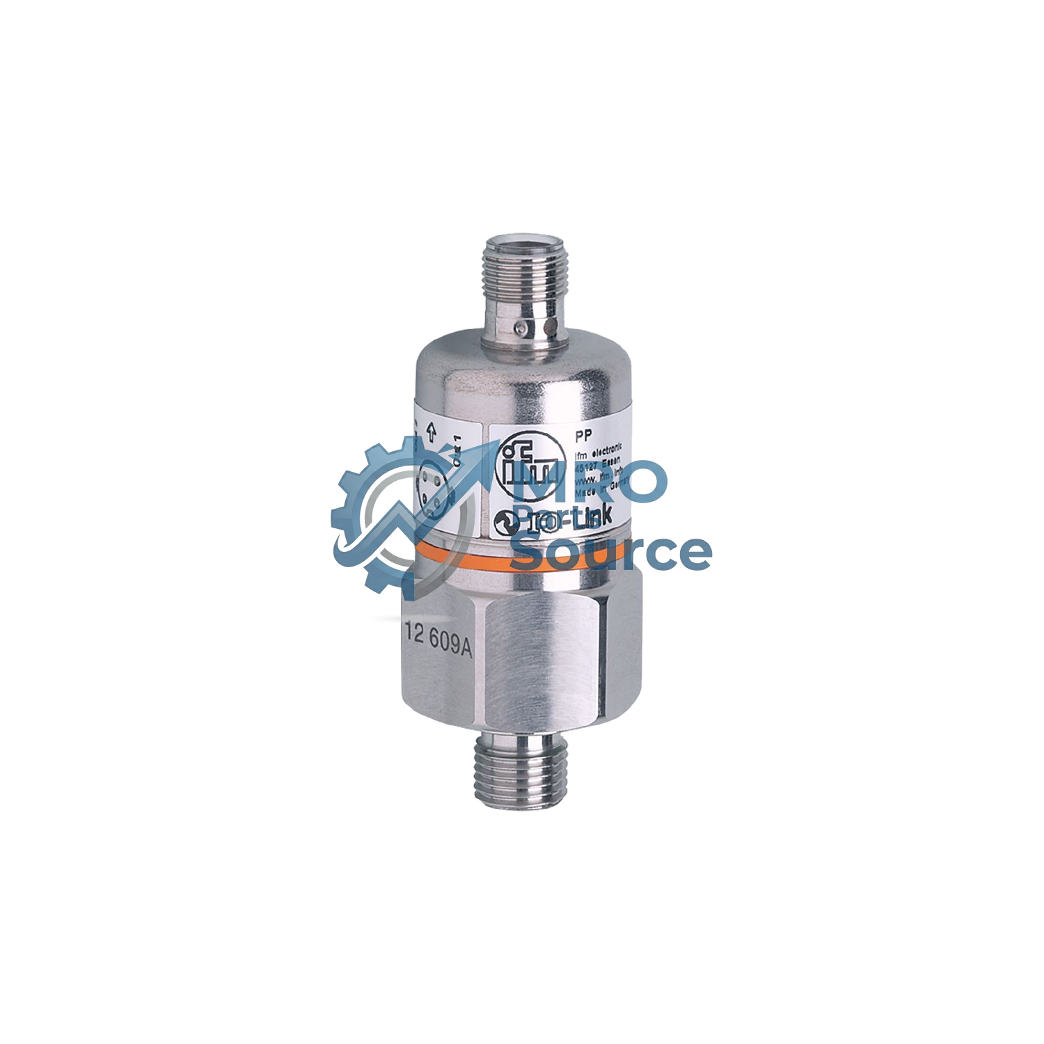
IFM PP7552 Pressure Sensors
Pressure switch with ceramic measuring cell
IFM PP7552 Pressure Sensors — datasheet, specifications, part number lookup & authentic sourcing
Get a Quote / Inquire
Product Highlights
- Robust design for use in harsh industrial environments
- Two switching outputs, one of which can be configured as diagnostic output
- High shock and vibration resistance
- Lifespan of more than 100 million pressure cycles
- User-friendly communication and parameterisation via IO-Link
Overview
| Product designation | Electronic pressure sensor |
| Application | for industrial applicationsfor railway applications |
| Process connection | threaded connection G 1/4 external thread internal thread:M5 |
| Operating voltage DC | 9.6...36 V |
| Voltage type | DC |
| Electrical design | PNP |
| Total number of outputs | 2 |
| Output function | normally open / normally closed; (parameterisable) |
| Output signal | switching signal; IO-Link; (configurable) |
| Measuring range | 0...100 bar0...1450 psi0...10 MPa |
| Connection | M12 Connector |
| Materials | stainless steel (304/1.4301); FKM; EPDM/X; PA |
| Materials (wetted parts) | stainless steel (303/1.4305); ceramics; FKM |
| Display | operation: 2 x LED green; switching status: 2 x LED yellow |
| Ambient temperature | -25...85 °C |
| Medium temperature | -25...90 °C |
| Communication interface | IO-Link |
| Brand | ifm electronic gmbh or equivalent |
| Type | PP7552 |
Specifications
| Product characteristics | |
| Number of inputs and outputs | Number of digital outputs: 2 |
| Measuring range | 0...100 bar 0...1450 psi 0...10 MPa |
| Process connection | threaded connection G 1/4 external thread internal thread:M5 |
| Application | |
| Application | for industrial applications; for railway applications |
| Media | liquids and gases |
| Conditionally suitable for | use in gases at pressures > 25 bar only on request |
| Medium temperature[°C] | -25...90 |
| Min. burst pressure | 650 bar 9400 psi 65 MPa |
| Pressure rating | 300 bar 4350 psi 30 MPa |
| Type of pressure | relative pressure |
| Electrical data | |
| Operating voltage[V] | 9.6...36 DC; (communication mode: 18...32) |
| Current consumption[mA] | < 45 |
| Min. insulation resistance[MΩ] | 100; (500 V DC) |
| Protection class | III |
| Reverse polarity protection | yes |
| Power-on delay time[s] | 0.3 |
| Inputs / outputs | |
| Number of inputs and outputs | Number of digital outputs: 2 |
| Outputs | |
| Total number of outputs | 2 |
| Output signal | switching signal; IO-Link; (configurable) |
| Electrical design | PNP |
| Number of digital outputs | 2 |
| Output function | normally open / normally closed; (parameterisable) |
| Max. voltage drop switching output DC[V] | 2 |
| Permanent current rating of switching output DC[mA] | 250 |
| Switching frequency DC[Hz] | 170 |
| Short-circuit protection | yes |
| Type of short-circuit protection | pulsed |
| Overload protection | yes |
| Measuring/setting range | |
| Measuring range | 0...100 bar 0...1450 psi 0...10 MPa |
| Set point SP | 1...100 bar 20...1450 psi 0.1...10 MPa |
| Reset point rP | 0.5...99.5 bar 10...1440 psi 0.05...9.95 MPa |
| In steps of | 0.5 bar 10 psi 0.05 MPa |
| Factory setting | |
| SP1 = 25.0 bar rP1 = 23.0 bar | |
| SP2 = 75.0 bar rP2 = 73.0 bar | |
| Accuracy / deviations | |
| Switch point accuracy[% of the span] | < ± 0,5 |
| Repeatability[% of the span] | < ± 0,1; (with temperature fluctuations < 10 K) |
| Characteristics deviation[% of the span] | < ± 0,25 (BFSL) / < ± 0,5 (LS); (BFSL = Best Fit Straight Line; LS = limit value setting) |
| Zero-point stabilisation[% of the span] | |
| switching output, display | 1,0 |
| Zero-point stabilisation[% of the span] | |
| IO-Link | 1,0; (see operating instructions zero-point behaviour) |
| Hysteresis deviation[% of the span] | < ± 0,1 |
| Long-term stability[% of the span] | < ± 0,1; (per year) |
| Temperature coefficient zero point[% of the span / 10 K] | < ± 0,2; (0...80 °C) |
| Temperature coefficient span[% of the span / 10 K] | < ± 0,2; (0...80 °C) |
| Response times | |
| Response time[ms] | < 3 |
| Damping process value dAP in steps[s] | 0,003 - 0,006 - 0,010 - 0,017 - 0,060 - 0,125 - 0,250 - 0,500 |
| Interfaces | |
| Communication interface | IO-Link |
| Transmission type | COM2 (38,4 kBaud) |
| IO-Link revision | 1.0 |
| SIO mode | yes |
| Required master port type | A |
| Process data analogue | 1 |
| Process data binary | 2 |
| Min. process cycle time[ms] | 2.3 |
| Supported DeviceIDs | |
| Type of operation | DeviceID |
| default | 4 |
| Operating conditions | |
| Ambient temperature[°C] | -25...85 |
| Storage temperature[°C] | -40...100 |
| Protection | IP 68; (7 days / 1 m water depth / 0.1 bar) |
| Tests / approvals | |
| EMC | |
| immunity | EN 61000-6-2 |
| EN 61000-4-2 ESD | 4 kV contact discharge / 15 kV air discharge |
| EN 61000-4-3 HF radiated | 20 V/m |
| EN 61000-4-4 Burst | 4 kV coupling clamp |
| EN 61000-4-5 Surge | 0,5 kV supply / 1 kV signal for DC units |
| EN 61000-4-6 HF conducted | 10 V |
| immunity | according to the automotive directive 1995/54/EC / 04/104EG / 05/83/EG |
| absorber chamber test to ISO 11452-2: | 80 V/m |
| Shock resistance | |
| DIN IEC 60068-2-27 / DIN IEC 60068-2-29 | 1000 g |
| DIN EN 61373 | category 3 |
| Vibration resistance | |
| DIN IEC 68-2-6 | 20 g (10...2000 Hz) |
| DIN EN 60068-2-64 | 14 g |
| DIN EN 61373 | category 2 |
| MTTF[years] | 310 |
| UL approval | |
| UL approval no. | J009 |
| Pressure Equipment Directive | Sound engineering practice; can be used for group 2 fluids; group 1 fluids on request |
| Railway applications | |
| DIN EN 50155 | Klasse T3, C1, S1 |
| Mechanical data | |
| Weight[g] | 228 |
| Housing | cylindrical |
| Dimensions[mm] | Ø 30 / L = 79.5 |
| Materials | stainless steel (304/1.4301); FKM; EPDM/X; PA |
| Materials (wetted parts) | stainless steel (303/1.4305); ceramics; FKM |
| Min. pressure cycles | 100 million |
| Process connection | threaded connection G 1/4 external thread internal thread:M5 |
| Restrictor element integrated | no (can be retrofitted) |
| Displays / operating elements | |
| Display | |
| operation | 2 x LED, green |
| switching status | 2 x LED, yellow |
| Teach function | yes |
| Remarks | |
| Pack quantity | 1 pcs. |
| Electrical connection | |
| Connector | 1 x M12; coding: A; Contacts: 4 |
Downloads
- PP7552 (233 KB)